 |
 |
Caution: Use at you OWN risk
This page contains information on setting the system speed jumper block on a BEIGE G3 motherboard. Parts of this information may apply to the BLUE & WHITE motherboard, or the G4 PCI GRAPHICS motherboard, but has not been verified.
If you set your clock speed to high your CPU will run unreliably. Sometimes it won't start at all, other times it will crash at start up or run for periods of time and then crash. You can cause damage to your processor or your motherboard easily by misusing this information. I take NO responsibility for any damage either direct or consequential you do by using this information. Use at your own risk. Whatever you do, please be careful.
1) Set a speed for the PCI slots bus portion of your system's bus.
2) Choose one of two allowable values to muliply the PCI speed setting by, which will set the SYSTEM bus speed. Note that many people believe that what you are setting is the System bus, and the multiplier is used negatively to set a lower PCI bus speed, but no apple engineer or person in the know has ever been able to confirm that for me. As is said: "six of one, a half-dozen of the other...".
The majority of G3 ZIF based processor modules understand up to the 8x multiple value, many also understand the 8.5 and 9.0x multiple values, and a small amount also allow up to 9.5x and 10x multiples. Note when purchasing a ZIF (be it G3 or G4 equipped) the highest multiple supported.
|
|
STEP 1 - Set the PCI Bus speed in megahertz. The stock setting is 33.3, and the lower and higher settings should only be used when you are sure you have PCI cards that are compatible. Be aware that not every motherboard functions optimally at every setting. I personally have had no problems with various Ethernet, SCSI, and Graphics cards in Beige G3s at the 35.0 PCI bus setting. Differences in components, motherboard revisions, and other factors lead to different performance and reliability out of motherboards from the same family.
| Pair Num. | . | PCI Speed | ||
| 7 | 8 | 9 | . | |
| S | S | - | . | 30.0 |
| S | - | - | . | 33.3 |
| - | S | S | . | 35.0 |
STEP 2 - Set the value to use to multiply the PCI bus speed by. This value will be used to multiply the PCI bus speed, and will set the SYSTEM bus speed. There are two allowable settings and values, 2.0 (short pairs 5 and 6) and 2.5 (shor pair 6 only). The value for shorting pair 5 only is apparently undocumented and should NOT be used.
| Pair Num. | . | PCI Multiplier | |
| 5 | 6 | . | |
| S | S | . | 2.0 |
| - | S | . | 2.5 |
STEP 3 - Set the value to use to multiply the SYSTEM bus speed by. This value will be used to multiply the SYSTEM bus speed, and will set the PROCESSOR speed. One should target this multiple at or near the rated speed of the processor being used. Many processors can be "overclocked" or set to operate at speeds slightly higher than the processor part rating. Overclocking with the Beige G3, Blue and White G3, and G4 PCI Graphics motherboards is extremely easy: simply set the following multiple for the system bus speed to a higher value than the value that corresponds to the processor rating. Overclocking in smaller increments can be achieved by leaving the following multiple at the proper setting for a processor, and altering the PCI speed or multiple in the previous steps.
NOTE: The jumper settings for 8.5x, 9x, 9.5x, and 10x are unknown and I believe unsupported on Beige G3 motherboards. The 83.3mhz. and 87.5mhz. Bus settings are highly unlikely to work at all, although I have heard of one or two users successfully running a Beige G3 motherboard at the 83.3mhz. System bus speed.
x
= unknown/undocumented, or highly unlikely to work.
Jumper Nr.
.
Multiplier
for Bus speed.
Resulting CPU clock speed
1
2
3
4
.
.
66.7MHz Bus
70.0MHz Bus
75.0MHz Bus
83.3MHz Bus
87.5MHz Bus
-
S
S
S
.
3.0
=
200
210
225
250
262.5
-
-
-
S
.
3.5
=
233
245
263
292
306
-
S
-
S
.
4.0
=
266
280
300
333
350
S
-
-
-
.
4.5
=
300
315
337
375
394
-
S
-
-
.
5.0
=
333
350
375
416
438
-
S
S
-
.
5.5
=
366
385
413
458
481
-
-
S
-
.
6.0
=
400
420
450
500
525
S
-
S
-
.
6.5
=
433
455
487
541
569
S
S
-
S
.
7.0
=
466
490
525
583
613
S
S
S
-
.
7.5
=
500
525
562
625
656
-
-
S
S
.
8.0
=
533
560
600
666
700
-
-
-
-
.
8.5
=
566
595
637
708
744
-
-
-
-
.
9.0
=
600
630
675
750
787
-
-
-
-
.
9.5
=
633
665
712
791
831
-
-
-
-
.
10.0
=
667
700
750
833
875
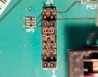
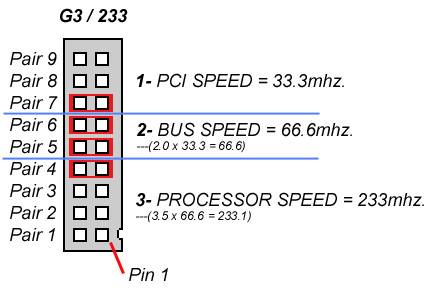
EXAMPLE - The pairs indicated by red rectangles denote pairs with jumpers in place to "short" the connection between the left and right pins in the pair.
OVERALL JUMPER SETTINGS CHART (Colors correspond to detail charts above)
|
|
|
|
|
(clock) |
(clock) |
(clock) |
(clock) |
(pci–mult) |
(pci–mult) |
(bus–mult) |
(bus–mult) |
(bus–mult) |
|||
|
|
|
|
|
|
|
|
|
|
|
|
|
|
|||
|
|
|
|
|
|
|
|
|
|
|
|
|
|
|||
|
|
|
|
|
|
|
|
|
|
|
|
|
|
|||
|
|
|
|
|
|
|
|
|
|
|
|
|
|
|||
|
|
|
|
|
|
|
|
|
|
|
|
|
|
|||
|
|
|
|
|
|
|
|
|
|
|
|
|
|
|||
|
|
|
|
|
|
|
|
|
|
|
|
|
|
|||
|
|
|
|
|
|
|
|
|
|
|
|
|
|
|||
|
|
|
|
|
|
|
|
|
|
|
|
|
|
|||
|
|
|
|
|
|
|
|
|
|
|
|
|
|
|||
|
|
|
|
|
|
|
|
|
|
|
|
|
|
|||
| 70.0 MHz | 35.0 MHz | 210 MHz | 3x | x | S | S | S | S | S | x | S | S | |||
| 70.0 MHz | 35.0 MHz | 245 MHz | 3.5x | x | x | x | S | S | S | x | S | S | |||
| 70.0 MHz | 35.0 MHz | 280 MHz | 4x | x | S | x | S | S | S | x | S | S | |||
| 70.0 MHz | 35.0 MHz | 315 MHz | 4.5x | S | x | x | x | S | S | x | S | S | |||
| 70.0 MHz | 35.0 MHz | 350 MHz | 5x | x | S | x | x | S | S | x | S | S | |||
| 70.0 MHz | 35.0 MHz | 385 MHz | 5.5x | x | S | S | x | S | S | x | S | S | |||
| 70.0 MHz | 35.0 MHz | 420 MHz | 6x | x | x | S | x | S | S | x | S | S | |||
| 70.0 MHz | 35.0 MHz | 455 MHz | 6.5x | S | x | S | x | S | S | x | S | S | |||
| 70.0 MHz | 35.0 MHz | 490 MHz | 7x | S | S | x | S | S | S | x | S | S | |||
| 70.0 MHz | 35.0 MHz | 525 MHz | 7.5x | S | S | S | x | S | S | x | S | S | |||
| 70.0 MHz | 35.0 MHz | 560 MHz | 8x | x | x | S | S | S | S | x | S | S | |||
|
|
|
|
|
|
|
|
|
|
|
|
|
|
|||
|
|
|
|
|
|
|
|
|
|
|
|
|
|
|||
|
|
|
|
|
|
|
|
|
|
|
|
|
|
|||
|
|
|
|
|
|
|
|
|
|
|
|
|
|
|||
|
|
|
|
|
|
|
|
|
|
|
|
|
|
|||
|
|
|
|
|
|
|
|
|
|
|
|
|
|
|||
|
|
|
|
|
|
|
|
|
|
|
|
|
|
|||
|
|
|
|
|
|
|
|
|
|
|
|
|
|
|||
|
|
|
|
|
|
|
|
|
|
|
|
|
|
|||
| 75 MHz | 30 MHz | 562 MHz | 7.5x | S | S | S | x | x | S | S | S | x | |||
| 75 MHz | 30 MHz | 600 MHz | 8x | x | x | S | S | x | S | S | S | x | |||
|
|
|
|
|
|
|
|
|
|
|
|
|
|
|||
|
|
|
|
|
|
|
|
|
|
|
|
|
|
|||
|
|
|
|
|
|
|
|
|
|
|
|
|
|
|||
|
|
|
|
|
|
|
|
|
|
|
|
|
|
|||
|
|
|
|
|
|
|
|
|
|
|
|
|
|
|||
|
|
|
|
|
|
|
|
|
|
|
|
|
|
|||
|
|
|
|
|
|
|
|
|
|
|
|
|
|
|||
|
|
|
|
|
|
|
|
|
|
|
|
|
|
|||
| 83 MHz | 33 MHz | 583 MHz | 7x | S | S | x | S | x | S | S | x | x | |||
| 83 MHz | 33 MHz | 625 MHz | 7.5x | S | S | S | x | x | S | S | x | x | |||
|
|
|
|
|
|
|
|
|
|
|
|
|
|